
Battery-Powered Wall Lamp
This project is about building a battery-powered wall lamp from scratch. The lamp has the following features:
- Battery-powered: It is powered by rechargeable NiMH batteries, i.e., no unsightly visible wires.
- Adjustable brightness: The brightness can be adjusted to suit different needs.
- Charging: The lamp can be charged using a 12V power supply.
- Automatic power-off: The lamp automatically turns off after a specified period.
The Finished Lamp
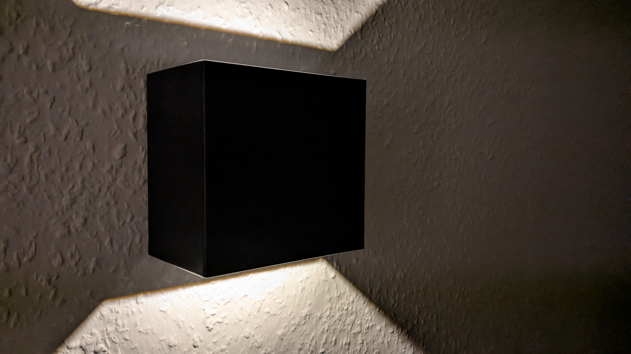
The lamp has a size of 11 cm × 11 cm × 7 cm (width × height × depth) and features a 2700 K LED. Depending on the brightness setting, the lamp can last up to 39 h on a single charge (around 20-30 h at medium brightness). This is enough for several days to a week of use if used for a few hours a day. The remainder of this article describes the design and implementation of the lamp in more detail.
The LED and Driver Module
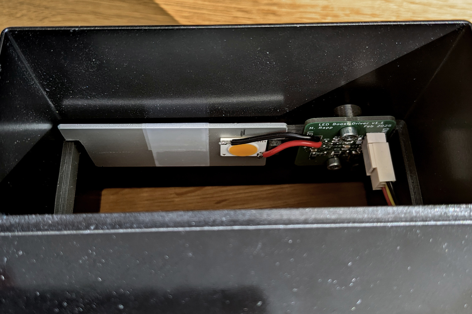
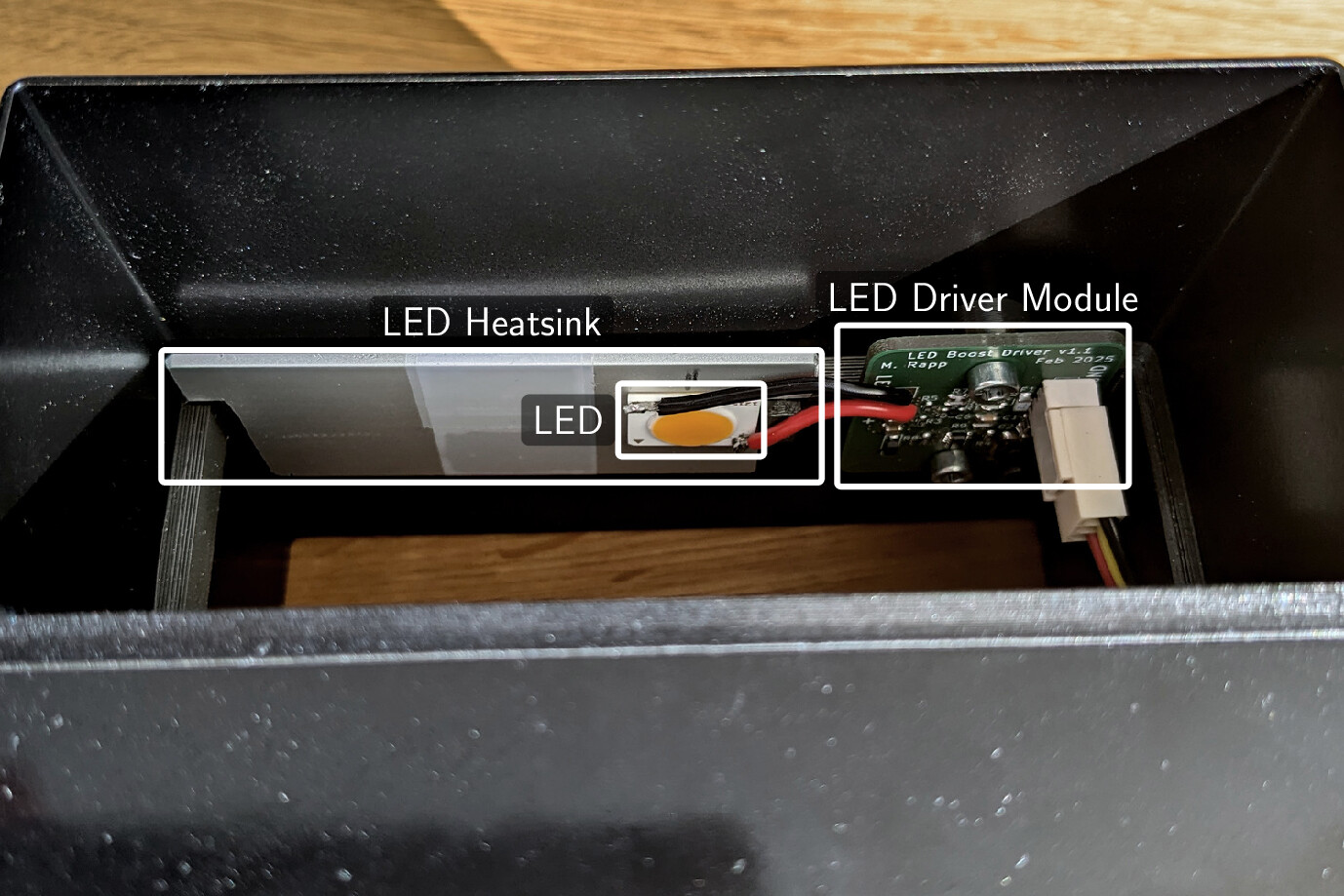
I decided to use a small and cheap LED that is mounted on a ceramic PCB. The LED is rated for 12 V and 550 mA, and provides a warm color temperature of 2700 K. At full brightness, the LED provides 710 lm, which is brighter than needed. Also, the 12 V rating means that I either need to use batteries with a voltage larger than 12 V or use a boost LED driver to step up the voltage. I decided to use a boost LED driver because it allows me to use more common batteries.
The LED driver is mounted on a small custom PCB that implements the following schematic (see below for details on how to compute the component values):
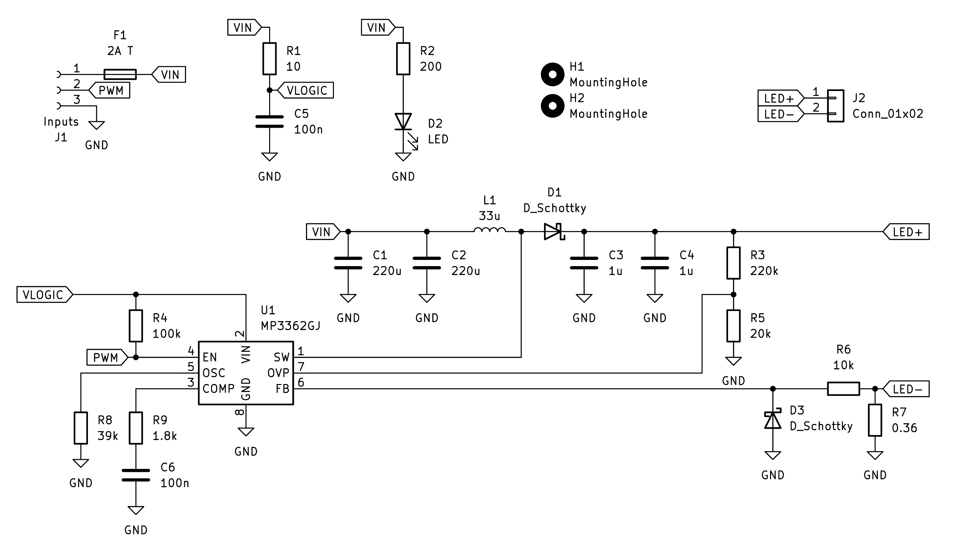
At its core, an MP3362 LED driver is used to maintain a constant 550 mA current through the LED. It also features a PWM input for dimming, which is exposed on the PCB.
The Main Control Module
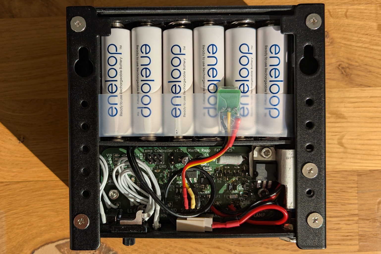
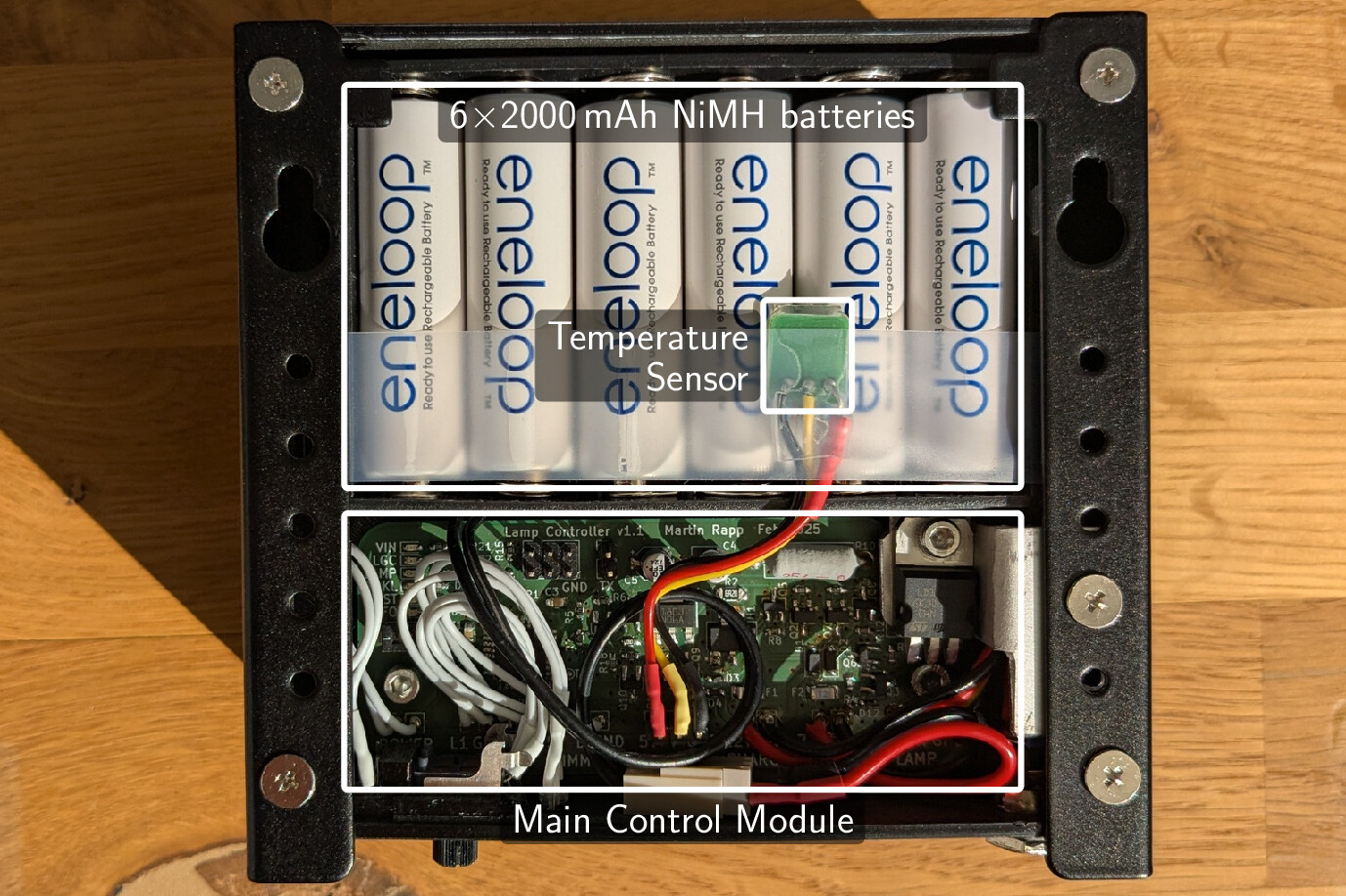
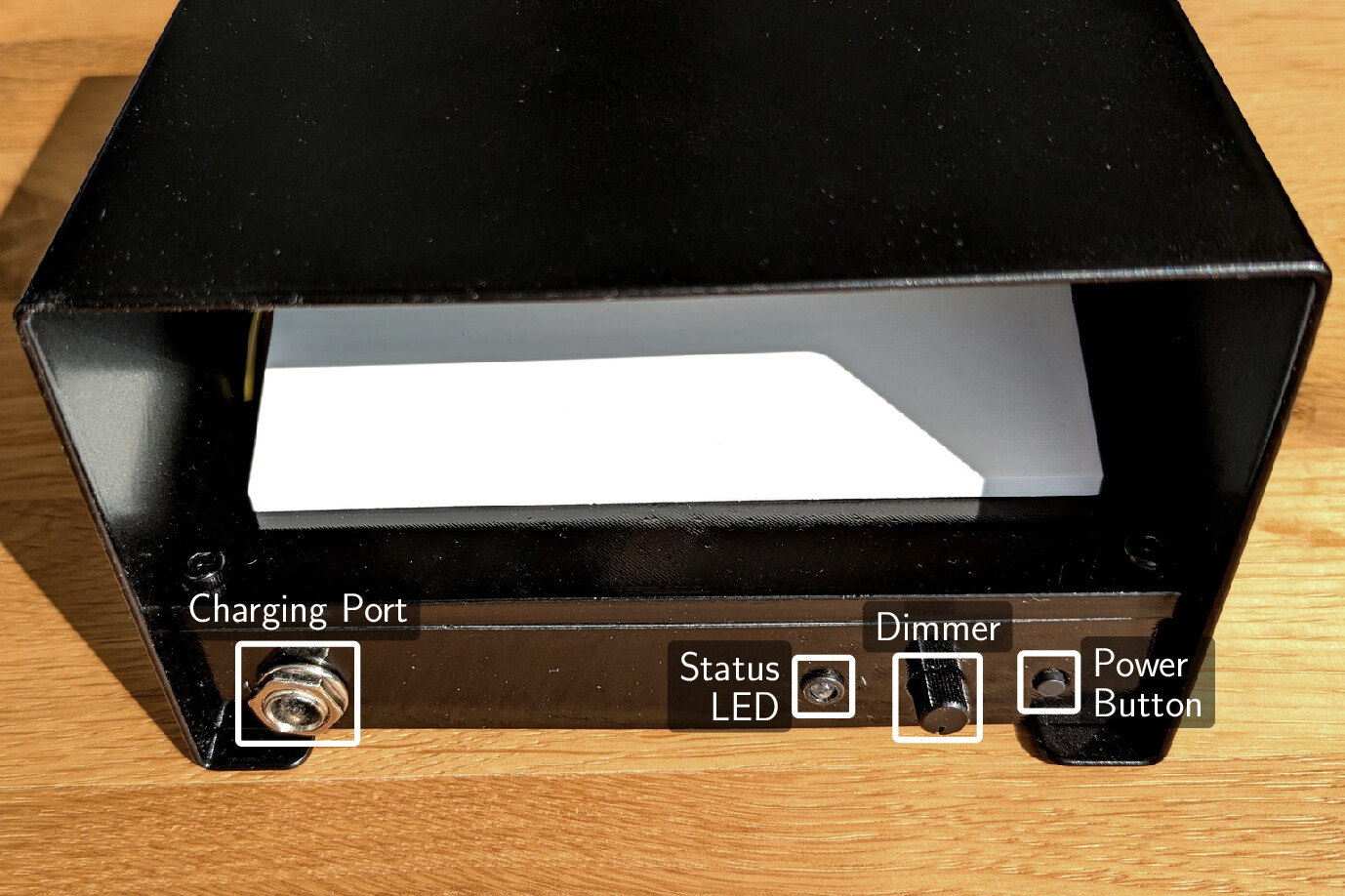
The second module is the main module, which implements the main control logic of the lamp and is connected to the controls. The following images show more details of the lamp, including the back side with the battery and main control module, as well as the control panel (swipe right for annotations and further images).
The main module implements this schematic:
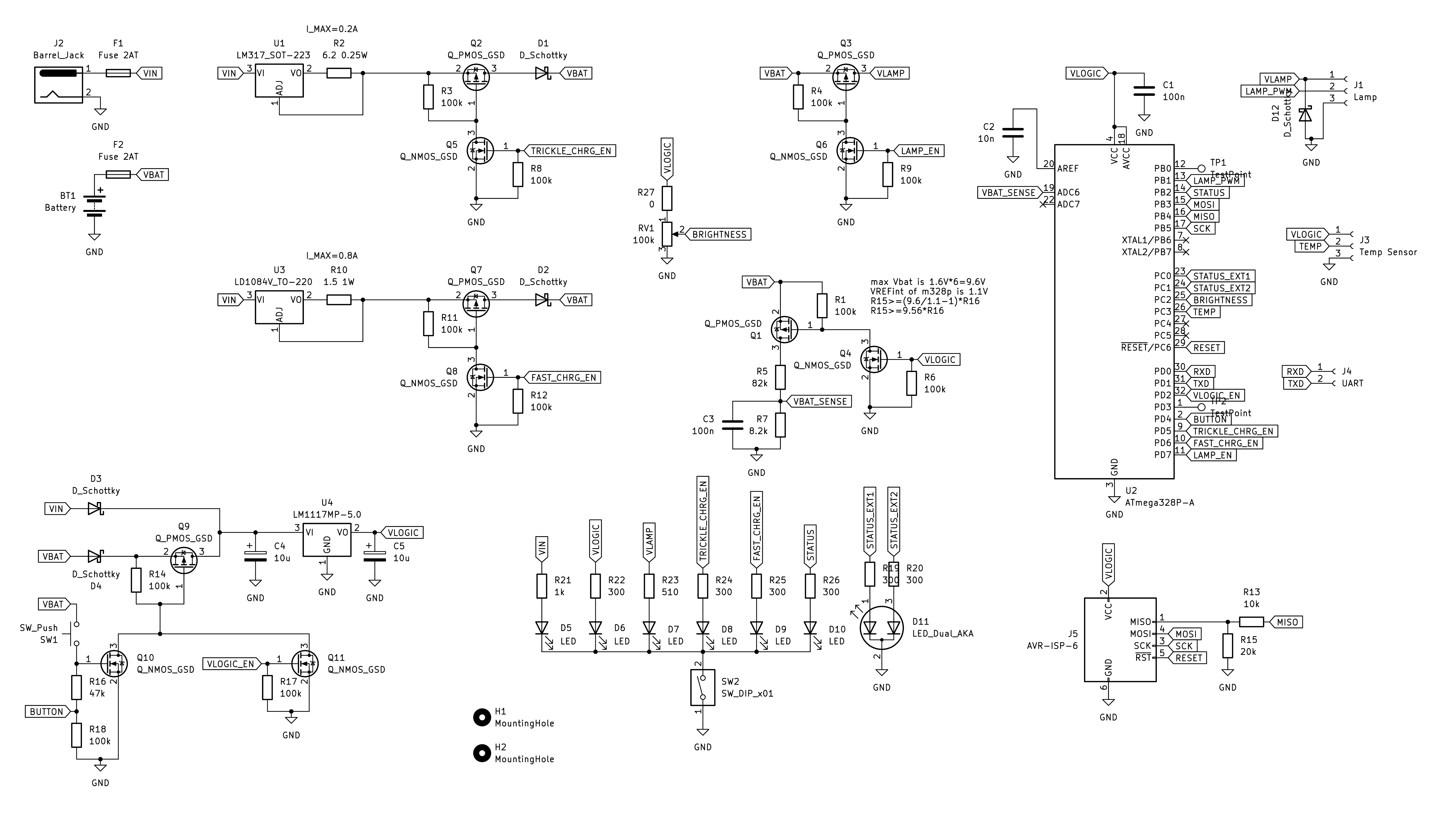
It supports the following power flows:
- Fast charging: VIN → battery (via U3, Q7, and D2), limited to 0.8 A. The microcontroller can enable or disable this power flow.
- Trickle charging: VIN → battery (via U1, Q2, and D1), limited to 0.2 A. The microcontroller can enable or disable this power flow.
- Powering the microcontroller from VIN: VIN → microcontroller (via D3 and U4). This power flow is hardwired.
- Powering the microcontroller from the battery: battery → microcontroller (via D4, Q9, and U4). The microcontroller can enable or disable this power flow. Pressing the button forces this power flow to be enabled.
- Powering the LED driver from the battery: battery → LED driver (via Q3). The microcontroller can enable or disable this power flow.
The circuit is designed so that the battery is completely disconnected from any load, including the microcontroller, when off— i.e., the microcontroller can disable its own power supply. Additionally, the microcontroller can measure the dimmer potentiometer level, the battery voltage, and the battery temperature (using a TC1046 temperature-to-voltage converter). It can also control the lamp LED brightness via PWM and uses two status LEDs (red/blue) to indicate the current state of the lamp.
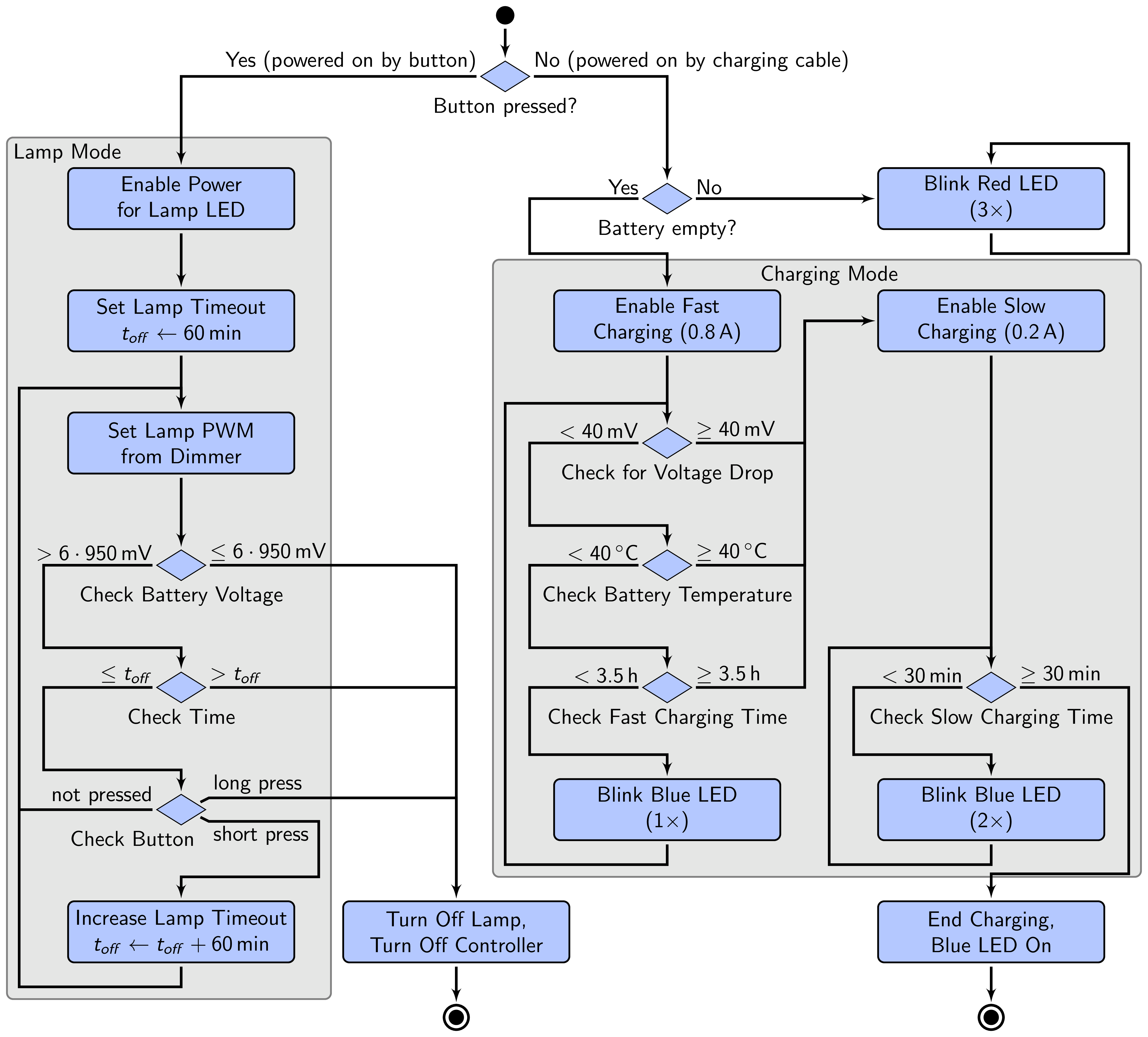
The control module implements three main operation modes:
- Lamp mode: The microcontroller is powered from the battery and provides power from the battery to the LED driver. The PWM duty cycle is set according to the dimmer potentiometer level using the following equation: and are the minimum and maximum brightness levels, respectively. They are set to 0.01 and 0.4, respectively. Exponential scaling results in a more natural brightness adjustment, as the human eye is more sensitive to brightness changes at low brightness levels. The lamp automatically turns off after 1 h. Each button press extends this time by 1 h. The lamp also turns off if the battery voltage drops below a specified threshold
- Charging mode: The microcontroller is powered from the charging connector, the battery is charged from the charging connector, and the LED driver is powered off.
Charging occurs in two phases:
- Fast charging: The battery is charged with a constant current of 0.8 A. End of charging is detected by monitoring the battery voltage and temperature. The fast charging process is stopped when the battery voltage drops by 40 mV or the battery temperature exceeds 40 °C. Credits to ChibiM and their excellent page about NiMH batteries at eneloop101.com, which was very helpful in understanding and designing the charging process.
- Trickle charging: The battery is charged with a constant current of 0.2 A for another 30 min to balance the cells.
The control flow of the operation modes is shown in the following flowchart (details omitted for clarity).
Batteries
I decided to use NiMH batteries. They do have lower energy density than Li-ion batteries, but they are safer to handle, as they are much less prone to catch fire. In the end, I decided to use six eneloop AA batteries, each rated for 2000 mAh and 1.2 V, i.e., around 14 Wh in total. The batteries are connected in series without cell balancing. As a consequence, I needed to select a bit more conservative charging parameters. After a few charging and discharging cycles, the batteries turned out to be well balanced (difference < 10 mV). However, I will keep an eye on this.
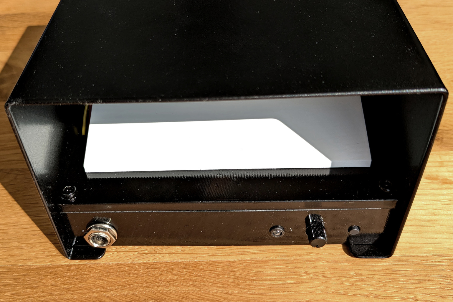
The Mechanical Design: Lampshade and Mounting
The lampshade and wall mount are made of sheet metal. The lampshade is powder-coated in matte black. All other parts are 3D-printed. The inside of the lamp features a white light diffuser opposite the LED to maximize the light output.
Charging and Discharging Measurements
The following charts show charging and discharging measurements of the lamp. All measurements were taken by the lamp itself, using the on-board microcontroller and sensors.
Charging:
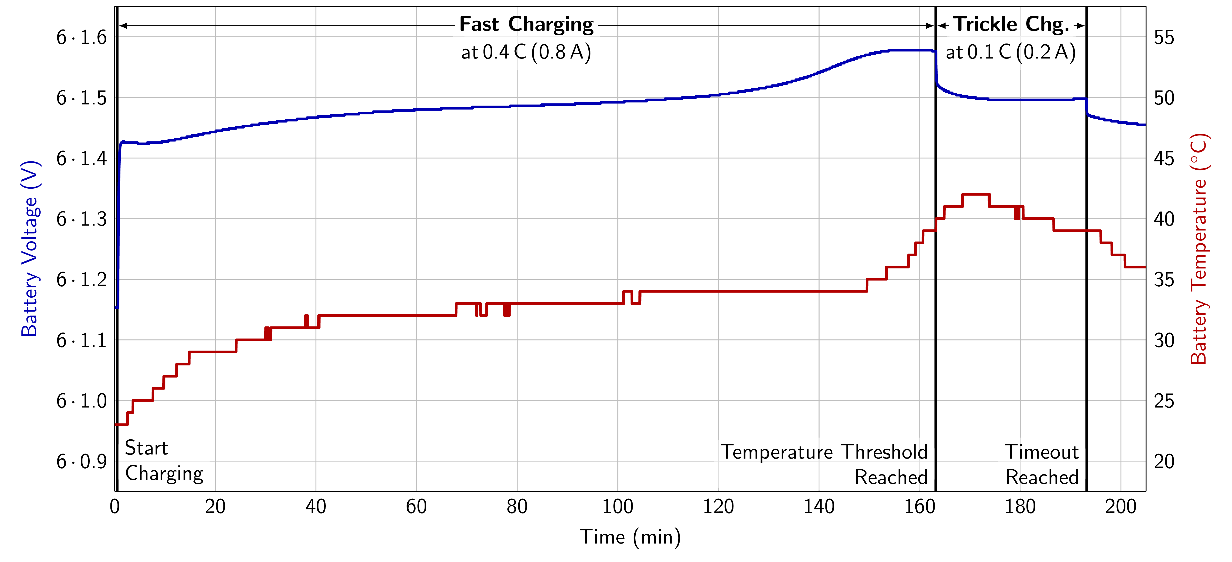
The charging process was logged by connecting the lamp to a PC, which periodically received measurement data via USB serial. In the first phase, the battery was charged with a constant current of 0.8 A (fast charging). After around 2 h, the battery voltage started to increase faster, indicating that the battery was almost fully charged. A bit later, at around 2.5 h the voltage plateaued and the temperature began to rise more rapidly. In this particular example, the temperature reached 40 °C before the battery voltage dropped significantly, stopping the charging process. Afterwards, the battery was charged with a constant current of 0.2 A (trickle charging) for another 30 min to balance the cells. During this phase, the temperature started to drop again.
Discharging:
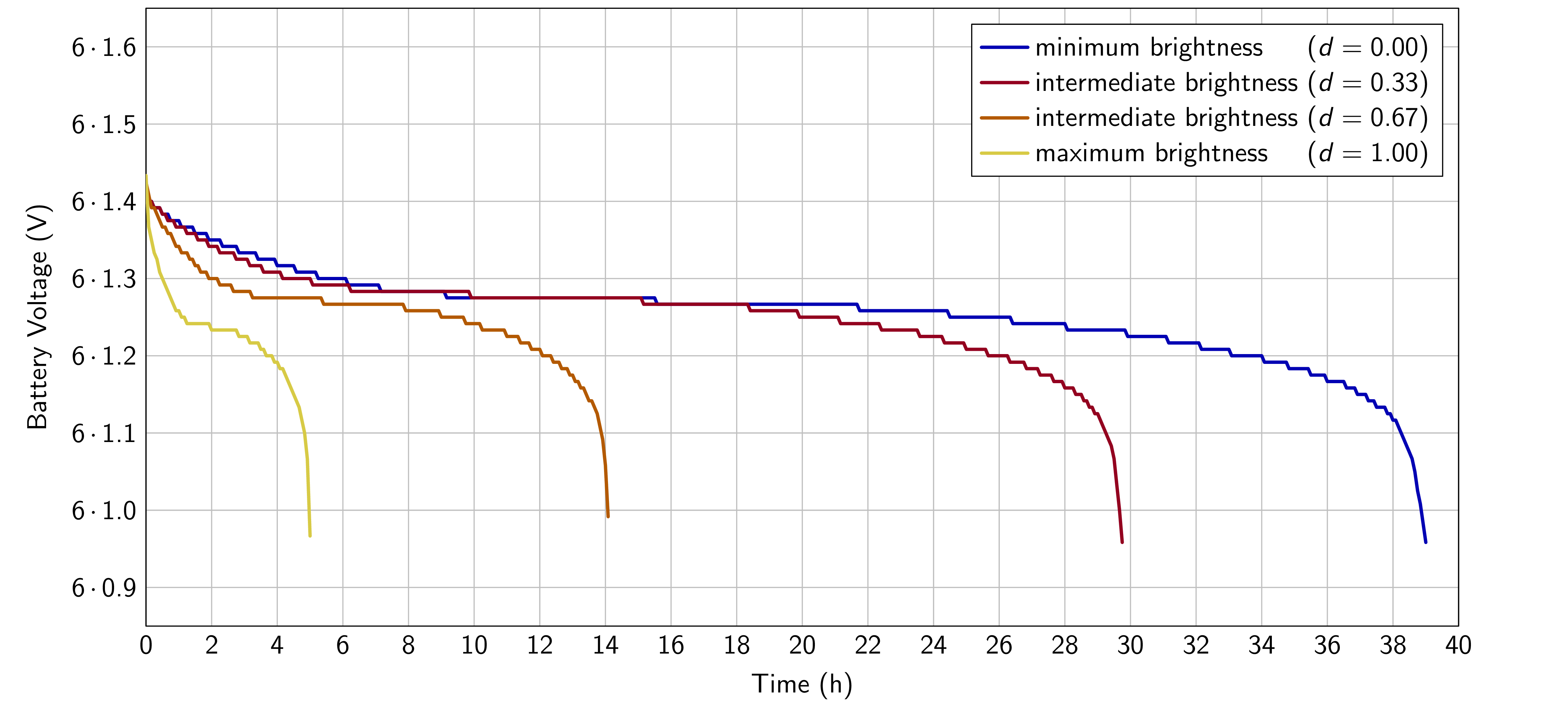
The discharging measurements are extracted from the lamp’s internal EEPROM, which logs the battery voltage and temperature every 5 minutes during operation. The measurement resolution is reduced to 50 mV to save space in the EEPROM. For this experiment, I let the lamp run at different brightness levels until the battery was empty. The intermediate brightness level corresponds to a realistic use case. In these settings, the battery lasted between 5 h and 39 h, with around 20-30 h at the intermediate brightness level. In day-to-day operation, the lamp will only be used for a few hours a day, so the battery will likely last several days, but that remains to be seen.
Final Thoughts
I am very happy with how the lamp turned out. I particularly like the minimalistic design. This also was my first battery-powered project and I learned a lot about NiMH battery management and charging.
There are a few things that I would do differently in hindsight:
- Power dissipation of the charging current: The charging circuit (particularly U3, see above) gets quite hot during charging. I would investigate using a more efficient charging circuit instead of the linear regulator. However, this would also increase the complexity of the circuit.
Additional Information: Computing the Component Requirements of the LED Boost Driver
The following tables summarize the computations for the LED driver, following the datasheet recommendations.
Values that are independent of the input voltage (battery voltage):
| Parameter | Description | Equation | (Selected) Value |
|---|---|---|---|
| Output voltage (LED voltage) | - | 12 V | |
| LED current | - | 550 mA | |
| Feedback resistor | 0.36 Ω | ||
| Feedback resistor power dissipation | 100 mW | ||
| Boost switching frequency | - | 1000 kHz | |
| Resistor for oscillator | 39 kΩ | ||
| PWM frequency | 1 kHz | ||
| Overvoltage protection level | 14.4 V | ||
| Output voltage drop | 0.12 V |
At :
| Parameter | Description | Equation | (Selected) Value |
|---|---|---|---|
| Input voltage (Battery voltage) | - | 6 V | |
| Average inductor current | 1.1 A | ||
| Inductor current swing | 0.33 A | ||
| Inductance | ≥8.9 μH | ||
| Inductor peak current | 1.3 A | ||
| Input voltage drop | 0.3 V | ||
| Input capacitance | ≥134 nF | ||
| Output capacitance | 2.2 μF |
At :
| Parameter | Description | Equation | (Selected) Value |
|---|---|---|---|
| Input voltage (Battery voltage) | - | 9 V | |
| Average inductor current | 0.73 A | ||
| Inductor current swing | 0.25 A | ||
| Inductance | ≥9.0 μH | ||
| Inductor peak current | 0.9 A | ||
| Input voltage drop | 0.3 V | ||
| Input capacitance | ≥104 nF | ||
| Output capacitance | 1.1 μF |
This leads to the following component requirements:
- Inductance: L≥8.9 μH, I≥1.3 A
- Input capacitance: C≥134 nF, U≥6 V, X7R recommended (but expensive, I used X5R)
- Output capacitance: C≥2.2 μF, U≥14.4 V, X7R recommended (but expensive, I used X5R)
- Diode: U≥1.2 =17 V, I≥3 =1.7 A, Schottky
- OVP resistors: 12.2
- reference schematic uses 300 kΩ
- =220 kΩ
- =20 kΩ
- Feedback resistor: R=0.36 Ω, P=100 mW
If you have questions or feedback, please don't hesitate to send me a mail: Your browser does not support Javascript