Home Air Quality Sensing
This project is about building an air quality sensor and corresponding dashboards. The main goals are to
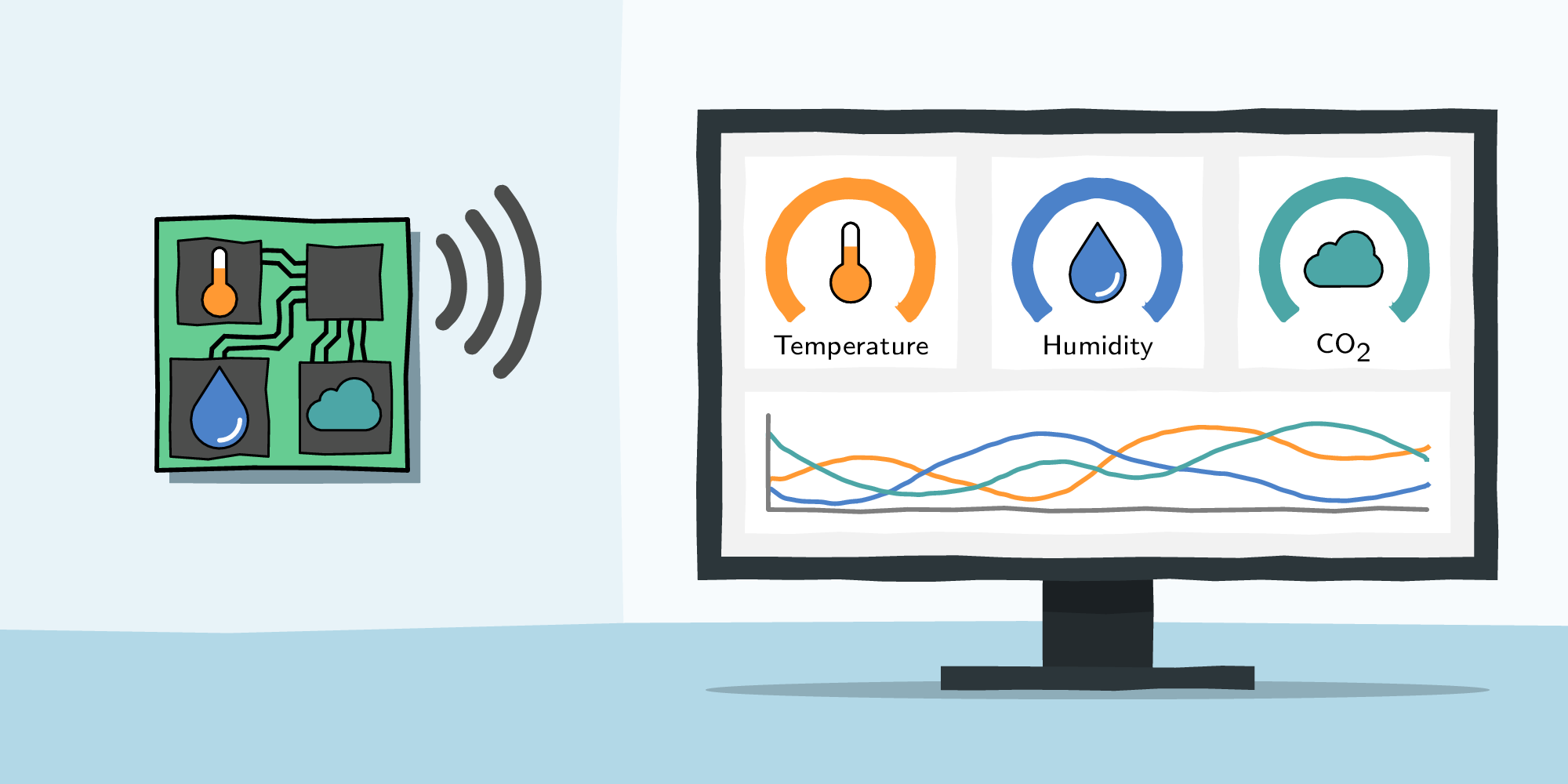
- measure the air quality (CO₂, temperature, and humidity) at several locations in our appartment,
- display the data on an interactive web dashboard, and
- display the data on an e-Paper display in our living room.
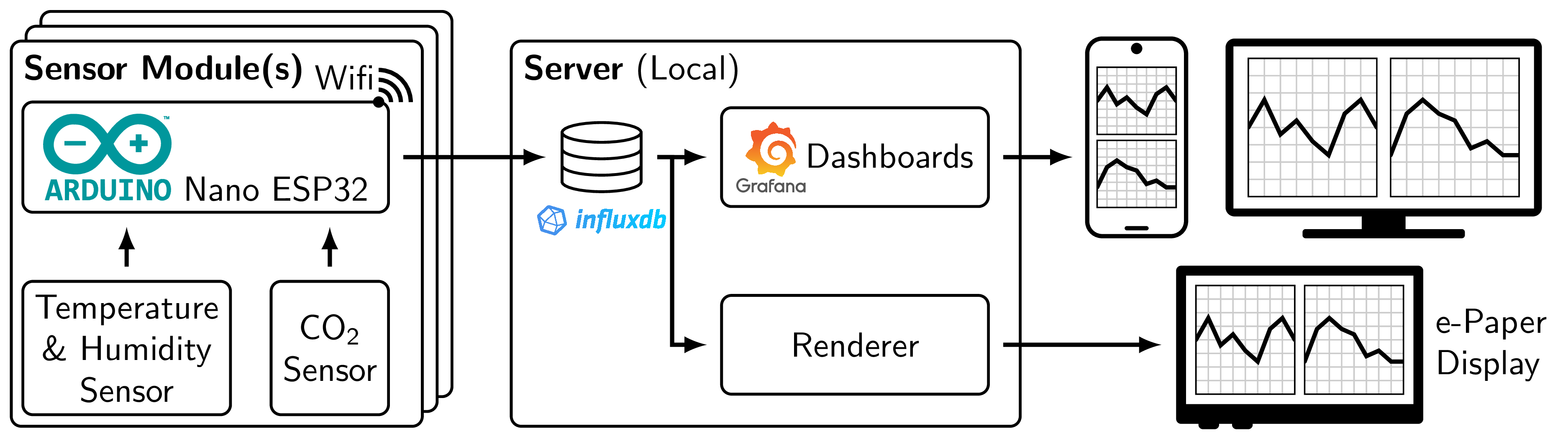
This article describes the hardware and software used for this project. The following figure shows all involved components and the information flow from the sensors via a server to the dashboards.
Sensor Modules
The sensor modules are based on
- an MH‑Z19C CO₂ sensor,
- a DHT22 temperature and humidity sensor, and
- an Arduino Nano ESP32 board with WiFi.
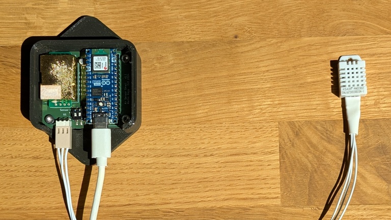
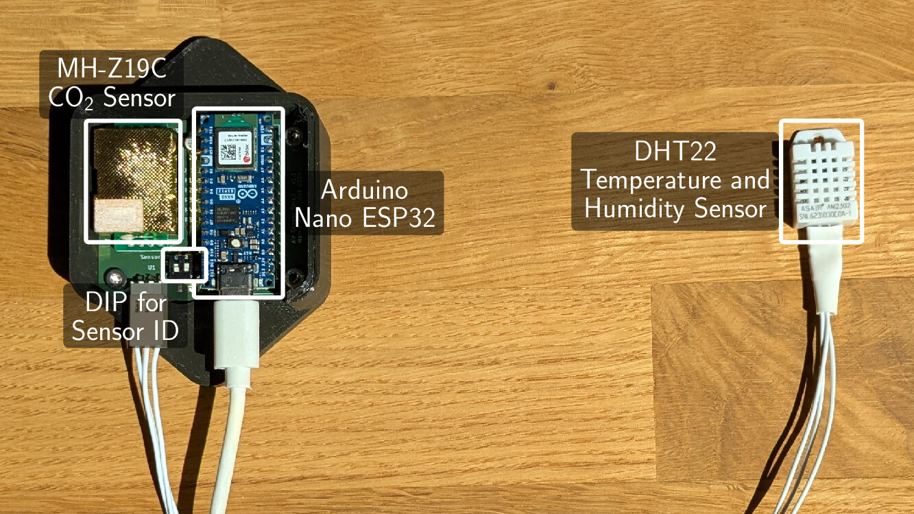
Each sensor module is assigned a separate ID via a DIP switch, which is used to identify the sensor measurements in the database and on the dashboard. A sensor module is powered by a 5V power supply, which is connected to the Arduino Nano ESP32 board. All components are connected on a custom PCB. The following image shows a sensor module, fully assembled with the Arduino Nano ESP32 and the MH‑Z19C, and mounted in a 3D-printed frame to mount it. This frame is designed to be mounted somewhere where it is not visible, e.g., behind a cupboard, hence the simple design. I have observed in an earlier version of the PCB that placing the DHT22 temperature sensor directly next to the MH‑Z19C sensor leads to an increase in the temperature readings by about 1°C. This is because the MH‑Z19C sensor uses an internal heater. To avoid that, the DHT22 sensor is placed far away from the PCB and connected to the PCB via a 3-wire cable.
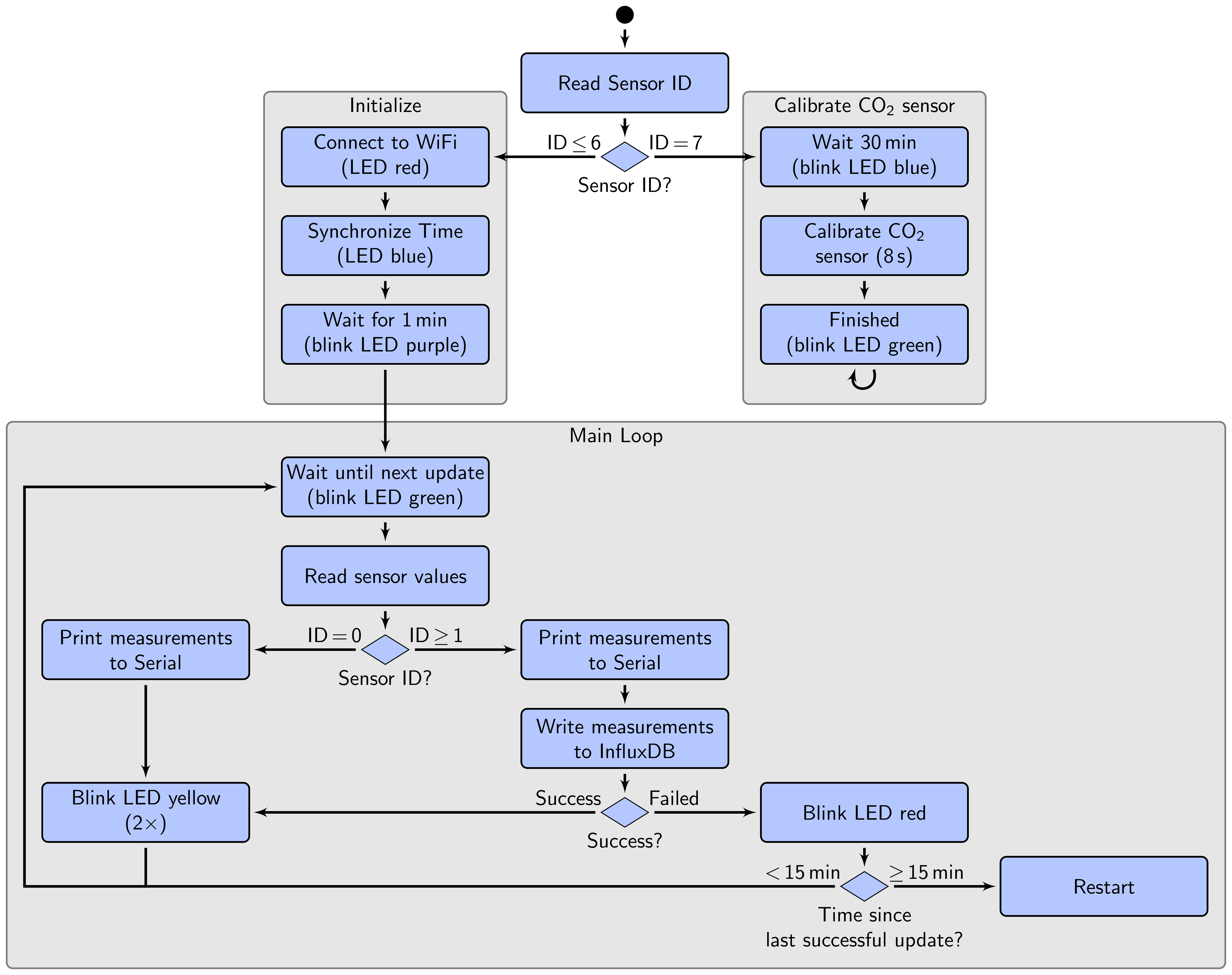
The software for the sensor module is based on the Arduino framework. The logic is quite simple and illustrated in the flowchart below. The main loop reads the CO₂ and temperature/humidity values from the sensors every minute and sends them to the InfluxDB database via WiFi. Additional features include calibration of the MH‑Z19C sensor by setting the sensor ID = 7.
The electronics (schematic and PCB design) and software sources are provided in the repositories linked at the bottom of this page.
Server: InfluxDB and Grafana Dashboard
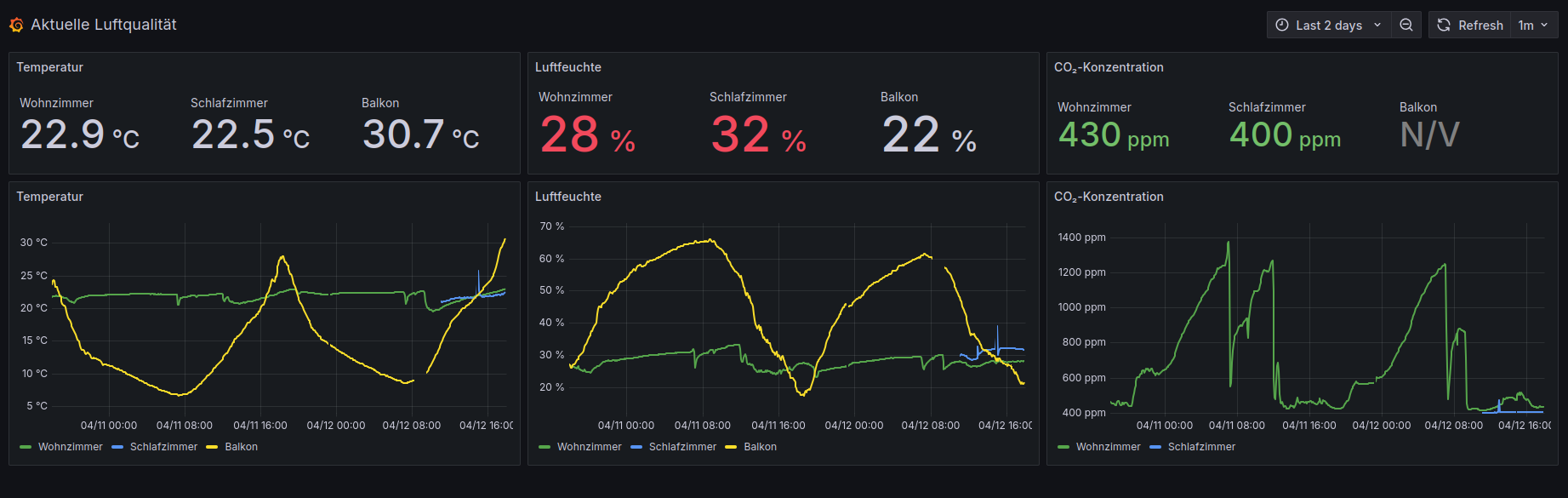
The InfluxDB and Grafana server run on a Raspberry Pi 5 with 8GB RAM. Here is a screenshot of the Grafana dashboard for illustration.
Dashboard on an e-Paper Display
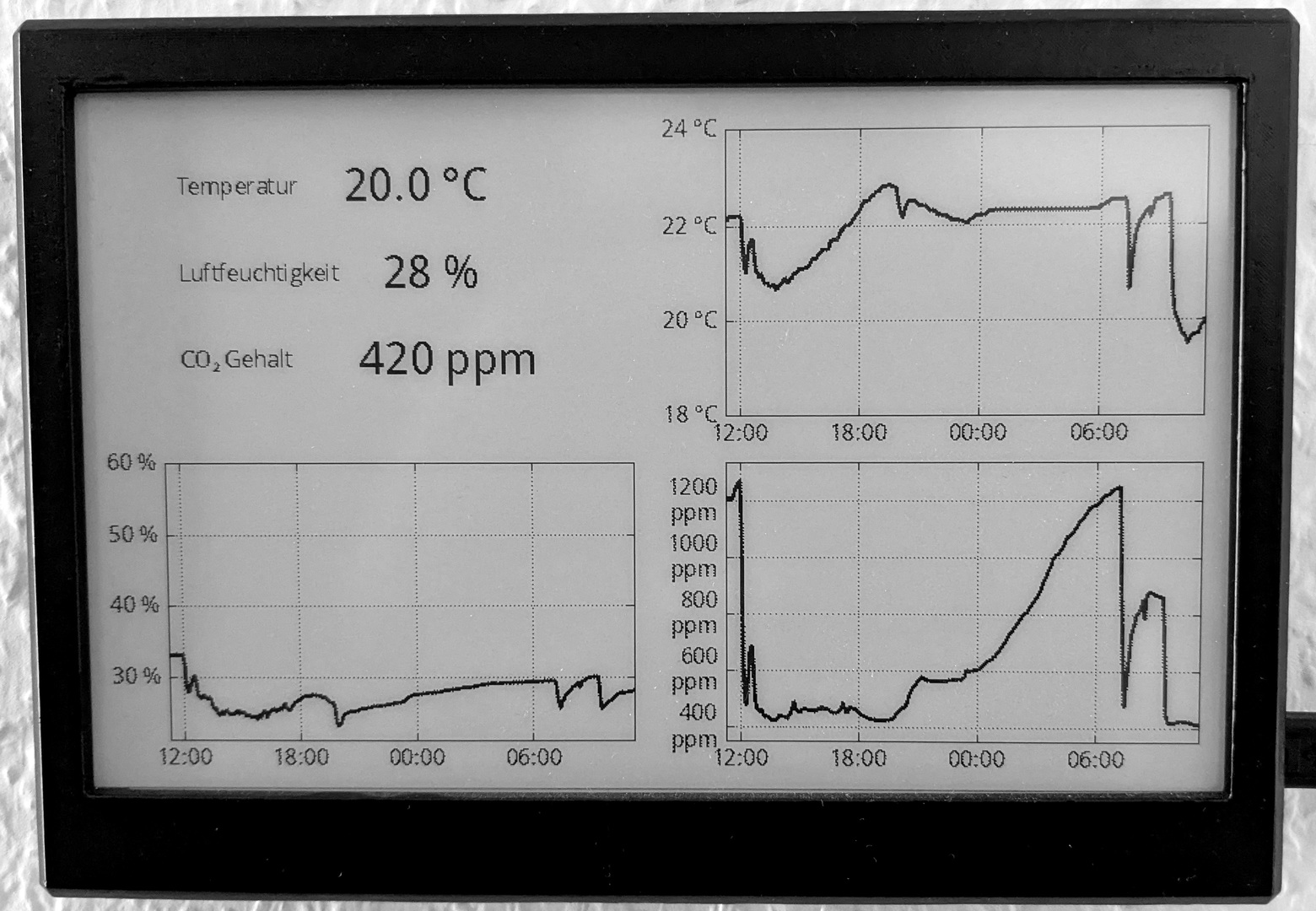
In addition to the Grafana dashboard, I also built a dashboard for my e-Paper display, which is mounted in our living room. The dashboard displays only the measurements of the sensor in the living room. For more details on how the e-Paper display and the corresponding server component are built, see the article about the weekly hiking quiz. The following image shows the e-Paper display with the dashboard.
The software sources for this part of the project are also provided in the repositories linked at the bottom of this page.
Final Thoughts
I am quite happy with the result. Finally, this project integrates nicely with the previously built weekly hiking quiz on the e-Paper display. I am barely using the Grafana dashboard, but I am looking at the e-Paper display a lot.
Nevertheless, there are a few things that I would do differently in hindsight:
- Time series database: I used InfluxDB 2, which comes with a rather unintuitive query language. Unfortunately, InfluxDB 2 has since been replaced by InfluxDB 3, which is not backwards compatible. As a result, I now need to adapt several components, including parts of the sensor module software, the Grafana dashboard, and the code for rendering the e-Paper display view. InfluxDB 3 also introduces a complex product portfolio, with various deployment options and associated limitations, which I honestly find quite confusing. Overall, I would likely choose a different time series database, ideally in combination with a message broker like MQTT to decouple some of the components.
- CO₂ sensor: I would look for a different CO₂ sensor. The auto-calibration feature of the MH‑Z19C is not very useful in inside environments, as it requires the sensor to be exposed to fresh air every 24 hours. I have observed significant jumps in the CO₂ values when the sensor is not exposed to fresh air for a while, e.g., when we are not home for a few days. Manual calibration drifts slowly over time, but there are large variations between sensors, where some barly drift, while others drift significantly. I am, however, not sure if there is a better alternative to the MH‑Z19C that is easy to use but still not too expensive.
Why not simply buy existing sensors? The simple answer is: because I wanted to build it myself—partly because I enjoy the process, partly to learn, and partly because I wanted to have full control over the features.
Sources
You can access the sources at the following links. This includes the software, electronics, and hardware design files of the sensors, as well as the software for the e-Paper display.
| Sensor Electronics and Software | https://github.com/ma-rapp/air-quality-sensors |
| e-Paper Server Software | https://github.com/ma-rapp/epaper-display-server |
| e-Paper Panel | https://github.com/ma-rapp/epaper-display-panel |
If you have questions or feedback, please don't hesitate to send me a mail: Your browser does not support Javascript